Hyundai Santa Cruz: Engine And Transaxle Assembly / Engine And Transaxle Assembly

• Use fender covers to avoid damaging painted surfaces.
• To avoid damage, unplug the wiring connectors carefully while holding the connector portion.

• To avoid damage, unplug the wiring connectors carefully while holding the connector portion.
1.Remove the engine cover.(Refer to Engine And Transaxle Assembly - “Engine Cover”)
2.Remove the air duct and air cleaner assembly.(Refer to Intake And Exhaust System - "Air Cleaner")
3.Remove the engine control module (ECM).(Refer to Engine Control/Fuel System - "Engine Control Module (ECM)")
4.Remove the battery and battery tray.(Refer to Engine Electrical System - "Battery")
5.Remove the engine room under cover.(Refer to Engine And Transaxle Assembly - “Engine Room Under Cover”)
6.Drain the engine coolant.(Refer to Cooling System - "Coolant")
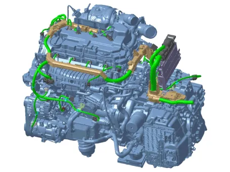
7.Disconnect the wiring connectors and harness clamps and remove the connector brackets around the engine and transaxle assembly.
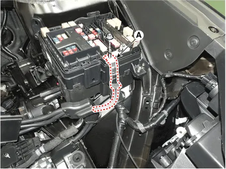
8.Disconnect the positive wiring cable (A).
Tightening torque :7.8 - 9.8 N.m (0.8 - 1.0 kgf.m, 5.8 - 7.2 lb-ft)
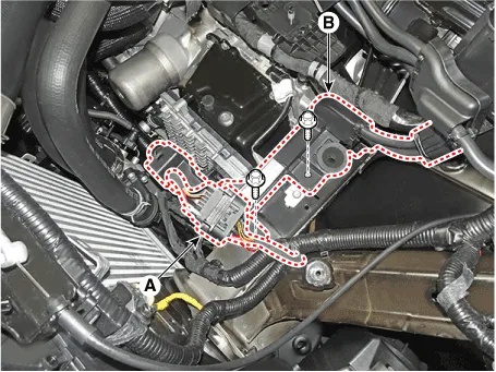
9.Disconnect the front connector (A) and remove the battery positive wiring protector (B).
Tightening torque :10.8 - 13.7 N.m (1.1 - 1.4 kgf.m, 8.0 - 10.1 lb-ft)
10.Disconnect the transaxle ground cable (A).
Tightening torque :10.8 - 13.7 N.m (1.1 - 1.4 kgf.m, 8.0 - 10.1 lb-ft)
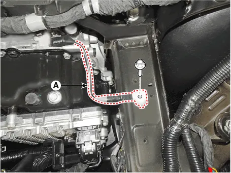
11.Disconnect the engine ground cable (A).
Tightening torque :10.8 - 13.7 N.m (1.1 - 1.4 kgf.m, 8.0 - 10.1 lb-ft)
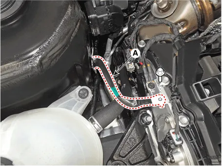
12.Remove the intercooler inlet hose & pipe (A) after loosen the bolt (B).
Tightening torque :14.7 - 19.6 N.m (1.5 - 2.0 kgf.m, 10.8 - 14.5 lb-ft)
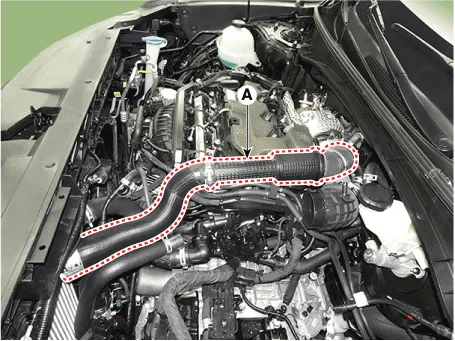
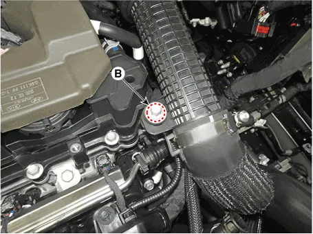

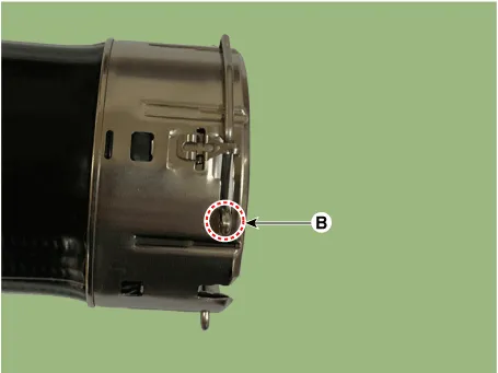
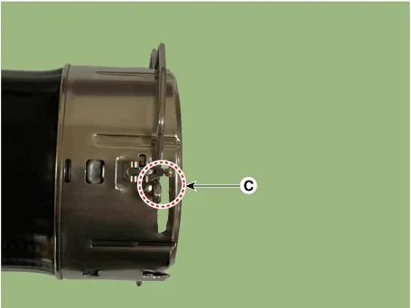
1)When disconnect the intercooler inlet hose, pull out the quick connector clamp (A) in the direction of the arrow as shown below.
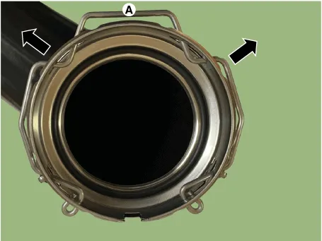
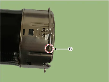
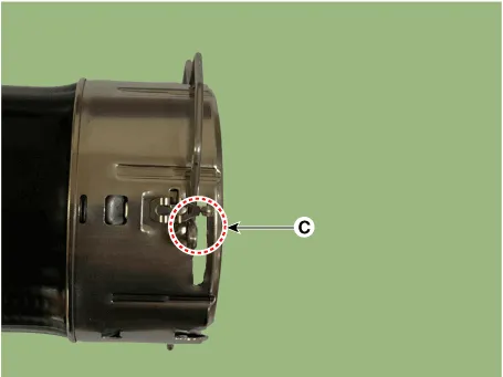
2)Move the quick connector clamp from position (B) to position (C) as shown below and pull out the quick connector hose.
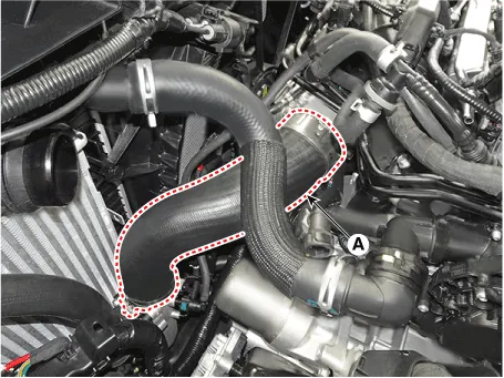
13.Disconnect the intercooler outlet hose (A).

1)When disconnect the intercooler inlet hose, pull out the quick connector clamp (A) in the direction of the arrow as shown below.
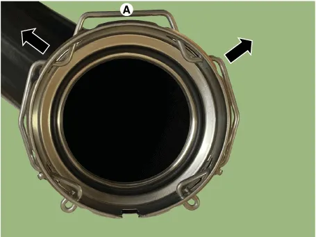
2)Move the quick connector clamp from position (B) to position (C) as shown below and pull out the quick connector hose.
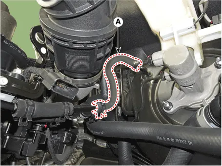
14.Disconnect the brake booster vacuum hose (A).
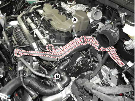
15.Disconnect the fuel hose (A) and purge control solenoid valve (PCSV) hose (B).
16.Disconnect the heater hoses (A).
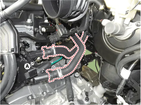
17.Disconnect the radiator upper hose (A).
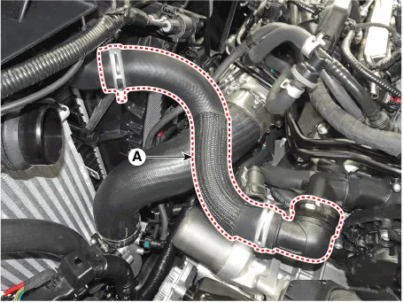
18.Disconnect the radiator lower hose (A).
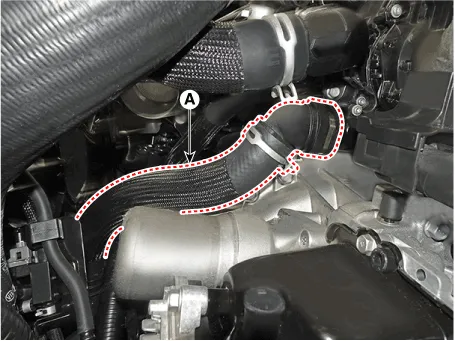
19.Disconnect reservoir tank hose (A).
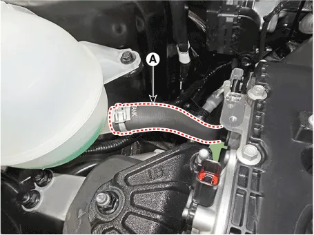
20.Recover the A/C refrigerant and then remove the high & low pressure pipes of A/C compressor. (Refer to Heating, Ventilation And Air Conditioning - "Compressor")
21.Remove the front muffler.(Refer to Intake And Exhaust System - "Muffler")
22.Remove the propeller shaft assembly. [4WD Only](Refer to Driveshaft and Axle - "Propeller Shaft Assembly")
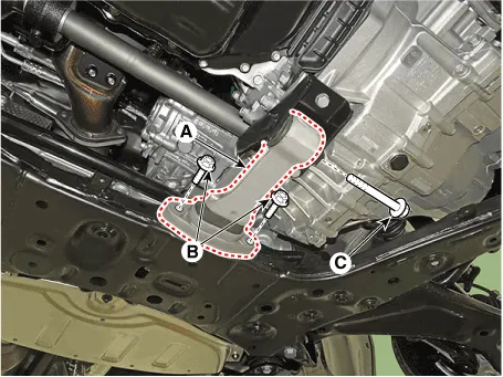
23.Remove the roll rod bracket (A).
Tightening torque :Bolts (B) : 49.0 - 63.7 N.m (5.0 - 6.5 kgf.m, 36.2 - 47.0 lb-ft)Bolt (C) :107.9 - 127.5 N.m (11.0 - 13.0 kgf.m, 79.6 - 94.0 lb-ft)

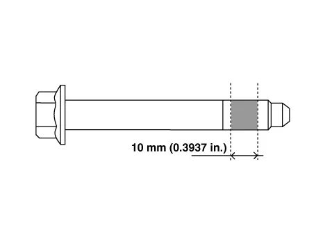
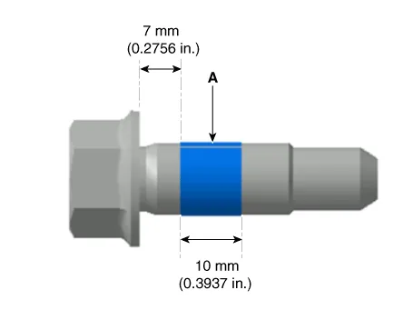
• The through bolt shall be replaced with freshness or applied with adhesive (3M 2353) to the bolt mark as shown below and then mounted as a tightening torque.
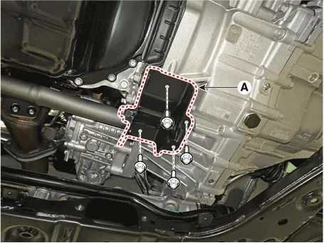
24.Remove the roll rod mounting support bracket (A).
Tightening torque :49.0 - 68.6 N.m (5.0 - 7.0 kgf.m, 36.2 - 50.6 lb-ft)
25.Remove the steering U - joint mounting bolt.(Refer to Steering System - "Steering Gear Box")
26.Remove the sub frame.(Refer to Suspension System - "Sub Frame")

• Loosen the subframe retaining bolt, which may cause the engine and transaxle assembly to fall, so support it safely by supporting the jack.
27.Support the engine and transaxle assembly safely with a floor jack.
28.Remove the engine mounting support bracket (A).
Tightening torque :107.9 - 127.5 N.m (11.0 - 13.0 kgf.m, 79.6 - 94.0 lb-ft)
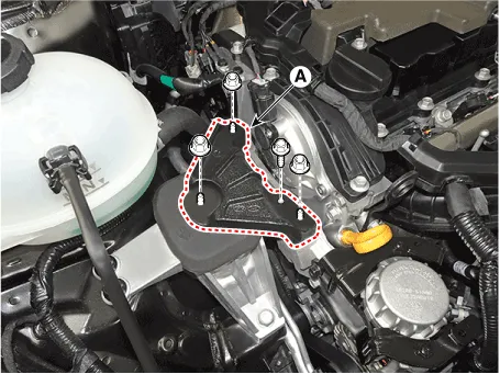

• Note the following items when working on the engine mounting bracket and the engine mounting support bracket.
• Always use a new engine mounting bracket and engine mounting support bracket securing nut.
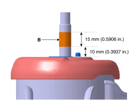
• Use a new bolt for fixing the engine mounting bracket or apply adhesive to the section of the bolt (A) as shown below.
• When installing the engine mounting support bracket : - Clean the hardened adhesive on the engine mounting bracket stud (B).- Reapply the adhesive to the engine mounting bracket studs (B) as shown below.
29.Remove the LH front wheel guard.(Refer to Body(Interior and Exterior) - "Front Wheel Guard")
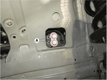
30.Remove the transaxle mounting bolts (A).
Tightening torque :107.9 - 127.5 N.m (11.0 - 13.0 kgf.m, 79.6 - 94.0 lb-ft)
31.Remove the engine and transaxle assembly by lifting vehicle.


• Before removing the engine and transaxle assembly, make sure hoses and wire connectors are disconnected.
• When removing the engine and transaxle assembly, be careful not to damage any surrounding parts or body components.
32.Install in the reverse order of removal.

• Refill a radiator and a reservoir tank with engine coolant.(Refer to Cooling System - "Coolant")
• Check the engine oil level.If necessary, refill engine with engine oil.
• Check the transaxle oil level.If necessary, refill a transaxle with fluid.
• Charging the refrigerant gas.
• Inspect for fuel leakage.
 Engine Mounting
- Components
1. Engine mounting support bracket2. Engine mounting bracket3. Transaxle mounting bracket4. Roll rod bracket
- Removal and Installation
Roll rod Bracket
1.Remove the engine ...
Other information:
Hyundai Santa Cruz (NX4A OB) 2021-2025 Service Manual: Identification Numbers
- Identification Number
Identification Number Description
Vehicle Identification Number
1.World Manufacturer Identifier (WMI)- 5NT : Freight
2.Vehicle line- J : NX4AT
3.Model & Series- A : Low grade (L)- B : Middle-Low grade (GL) - C : Middle grade (GLS, JSL, TAX) - D : Middle-H ...
Hyundai Santa Cruz (NX4A OB) 2021-2025 Service Manual: Rear Upper Arm
- Removal
• When lifting a vehicle using a lift, be careful not to damage
the lower parts of the vehicle (floor under cover, fuel filter, fuel
tank, canister).(Refer to General Information - "Lift and Support
Points")
1.Loosen the rear wheel nuts slightly.Raise the v ...

