Hyundai Santa Cruz: Engine And Transaxle Assembly / Engine Mounting
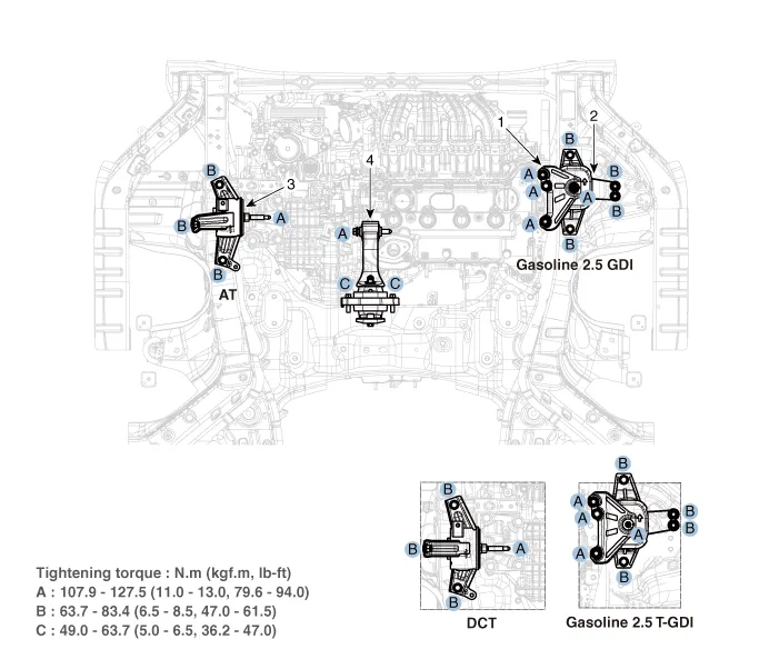
1. Engine mounting support bracket
2. Engine mounting bracket
3. Transaxle mounting bracket
4. Roll rod bracket
1.Remove the engine room under cover.(Refer to Engine And Transaxle Assembly- "Engine Room Under Cover")
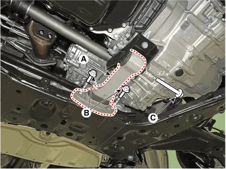
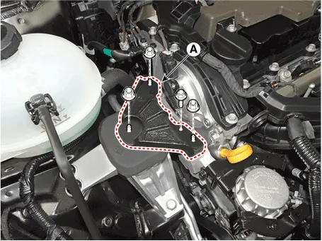
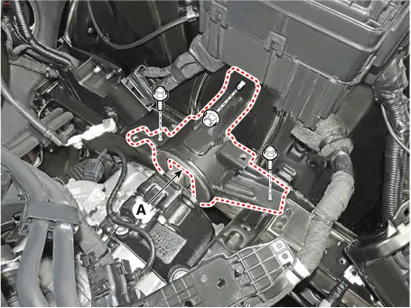
2.Remove the roll rod bracket (A).
Tightening torque Bolts (B) : 49.0 - 63.7 N.m (5.0 - 6.5 kgf.m, 36.2 - 47.0 lb-ft)Bolt (C) : 107.9 - 127.5 N.m (11.0 - 13.0 kgf.m, 79.6 - 94.0 lb-ft)

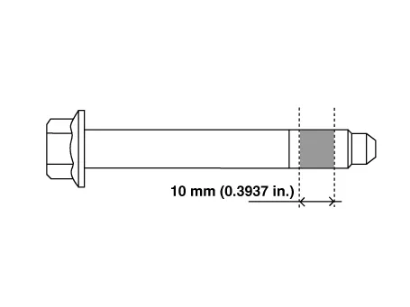
• The through bolt shall be replaced with freshness or applied with adhesive (3M 2353) to the bolt mark as shown below and then mounted as a tightening torque.
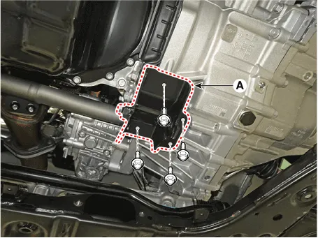
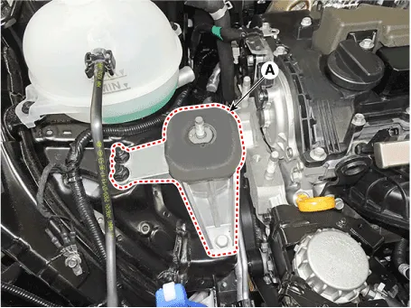
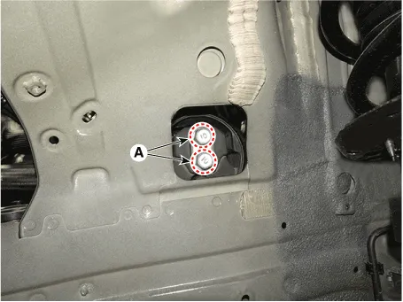
3.Remove the roll rod mounting support bracket (A).
Tightening torque :49.0 - 68.6 N.m (5.0 - 7.0 kgf.m, 36.2 - 50.6 lb-ft)
4.Install in the reverse order of removal.
1.Remove the engine room under cover.(Refer to Engine And Transaxle Assembly- "Engine Room Under Cover")
2.Install the jack to the edge of oil pan to support the engine.

• Insert the rubber block between jack and oil pan.
3.Remove the engine mounting support bracket (A).
Tightening torque :107.9 - 127.5 N.m (11.0 - 13.0 kgf.m, 79.6 - 94.0 lb-ft)
4.Remove the engine mounting bracket (A).
Tightening torque : 63.7 - 83.4 N.m (6.5 - 8.5 kgf.m, 47.0 - 61.5 lb-ft)
5.Install in the reverse order of removal.

• Note the following items when working on the engine mounting bracket and the engine mounting support bracket.
• Always use a new engine mounting bracket and engine mounting support bracket securing nut.
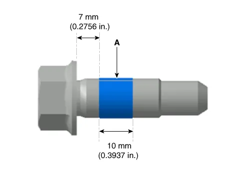
• Use a new bolt for fixing the engine mounting bracket or apply adhesive to the section of the bolt (A) as shown below.
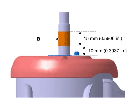
• When installing the engine mounting support bracket-Clean the hardened adhesive on the engine mounting bracket stud (B).-Reapply the adhesive to the engine mounting bracket studs (B) as shown below.
1.Remove the air duct and air cleaner assembly.(Refer to Intake And Exhaust System - "Air Cleaner")
2.Remove the engine control module (ECM).(Refer to Engine Control / Fuel System - "Engine Control Module (ECM)")
3.Remove the battery and battery tray.(Refer to Engine Electrical System - "Battery")
4.Remove the engine room under cover.(Refer to Engine And Transaxle Assembly - "Engine Room Under Cover")
5.Install the jack to the edge of transaxle.

• Insert the rubber block between jack and oil pan.
6.Remove the LH front wheel guard.(Refer to Body(Interior and Exterior) - "Front Wheel Guard")
7.Remove the transaxle mounting bolts (A).
Tightening torque : 107.9 - 127.5 N.m (11.0 - 13.0 kgf.m, 79.6 - 94.0 lb-ft)
8.Remove the transaxle mounting bracket (A).
Tightening torque : 63.7 - 83.4 N.m (6.5 - 8.5 kgf.m, 47.0 - 61.5 lb-ft)
9.Install in the reverse order of removal.
 Engine Room Under Cover
- Removal and Installation
1.Remove the engine room under cover (A).Tightening torque :7.8 - 11.8 N.m (0.8 - 1.2 kgf.m, 5.8 - 8.7 lb-ft)
2.Install in the reverse order of removal. ...
 Engine And Transaxle Assembly
- Removal and Installation
• Use fender covers to avoid damaging painted surfaces.
• To avoid damage, unplug the wiring connectors carefully while holding the connector ...
Other information:
Hyundai Santa Cruz (NX4A OB) 2021-2025 Service Manual: Drive Belt
- Removal
1.Remove engine room under cover.(Refer to Engine And Transaxle Assembly - "Engine Room Under Cover")
2.Remove the drive belt (A).
• To release the tensioner, rotate the tensioner by turning the tensioner arm boss (A) clockwise using a wrench.
3.Remove t ...
Hyundai Santa Cruz 2021-2025 Owners Manual: Selecting a Child Restraint
System (CRS)
When selecting a Child Restraint System
for your child, always:
Make sure the Child Restraint System
has a label certifying that it meets
applicable Federal Motor Vehicle
Safety Standards (FMVSS 213).
Select a Child Restraint System based
on your child’s height and weight. The
requir ...
