Hyundai Santa Cruz: Transfer Assembly / Front Wheel Transfer Assembly

• Be careful not to damage the parts located under the vehicle (floor under cover, fuel filter, fuel tank and canister) when raising the vehicle using the lift.(Refer to General Information - "Lift and Support Points")
1.Remove the engine room under cover.(Refer to Engine Mechanical System - "Engine Room Under Cover")
2.Remove the front driveshaft assembly. [Right side](Refer to Driveshaft and Axle - "Front Driveshaft")
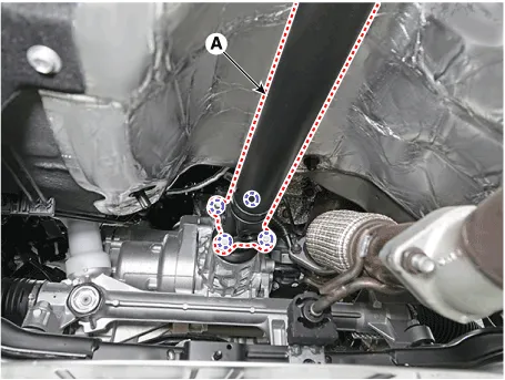
3.Remove the front propeller shaft assembly (A) from the transfer assembly.
Tightening torque :49.0 - 68.6 N.m (5.0 - 7.0 kgf.m, 36.2 - 50.6 lb-ft)
4.Remove the transfer case assembly.
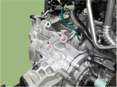
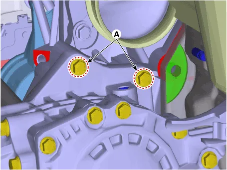
(1)Loosen the transafer assembly upper mounting bolts (A).
Tightening torque :60.8 - 65.7 N.m (6.2 - 6.7 kgf.m, 44.8 - 48.5 lb-ft)
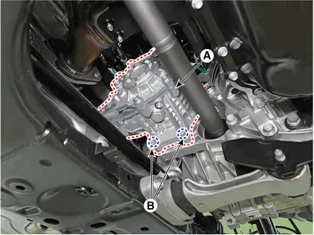
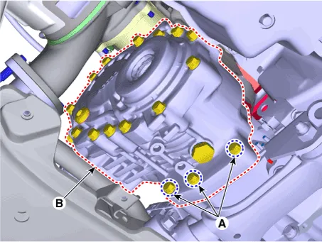
(2)Loosen the lower mounting bolts (A) and then removing the transfer case assembly (B).
Tightening torque :60.8 - 65.7 N.m (6.2 - 6.7 kgf.m, 44.8 - 48.5 lb-ft)

• Be careful not to damage the parts located under the vehicle (floor under cover, fuel filter, fuel tank and canister) when raising the vehicle using the lift.(Refer to General Information - "Lift and Support Points")
1.Remove the engine room under cover.(Refer to Engine Mechanical System - "Engine Room Under Cover")
2.Remove the front drive shaft assembly. [Right side](Refer to Driveshaft and Axle - "Front Driveshaft")
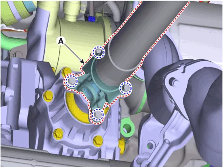
3.Remove the front propeller shaft assembly (A) from the transfer assembly.
Tightening torque :49.0 - 68.6 N.m (5.0 - 7.0 kgf.m, 36.2 - 50.6 lb-ft)
4.Remove the transfer case assembly.
(1)Loosen the transafer assembly upper mounting bolts (A).
Tightening torque :60.8 - 65.7 N.m (6.2 - 6.7 kgf.m, 44.8 - 48.5 lb-ft)
(2)Loosen the lower mounting bolts (A) and then removing the transfer case assembly (B).
Tightening torque :60.8 - 65.7 N.m (6.2 - 6.7 kgf.m, 44.8 - 48.5 lb-ft)
1.To install, reverse the removal procedures.

• Be careful not to damage the O-ring (A). If the O-ring is damaged, replace with a new one.
• Smear and cover splines (B) with molybdenum type high pressure grease.
GREASE SPL-1 equivalent (MS511-07)
[A Type]
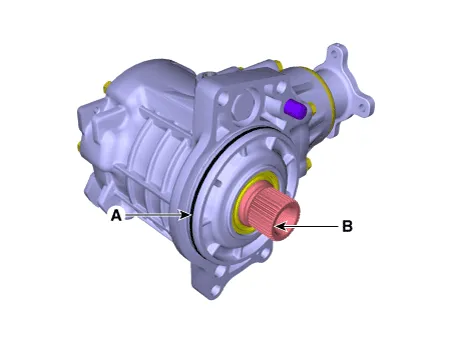
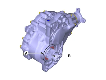
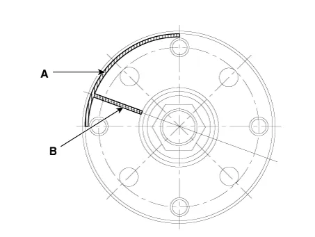
• Install the propeller shaft to be near runout marking (Transfer assembly 1ea (A), propeller shaft 1ea (B) each other.
 Transfer Fluid
- Inspection
• Transfer oil should be inspected and refilled every 60,000 km (40,000 mile) / 4 year.
• Be careful not to damage the parts located under ...
 Oil Seal
- Component
[A Type]
1. Transfer Case2. Oil seal (Transaxle side)
[B Type]
1. Dust cover2. Oil seal #1 (Drive shaft side)3. Oil seal #2 (Drive shaft side)4. Oil seal #3 (Drive shaft si ...
Other information:
Hyundai Santa Cruz (NX4A OB) 2021-2025 Service Manual: Repair procedures
- Refrigerant System Service Basics
Refrigerant Identification
• Do not mix HFO-1234yf (R-1234yf) in the vehicle with other refrigerant, such as R-12, R-134a and etc.
• Use only service equipment that is U.L-listed and is certified to
meet the requirements of SAE standards to recover a ...
Hyundai Santa Cruz (NX4A OB) 2021-2025 Service Manual: Heater & A/C Control Unit (Manual)
- Terminal Function
Connector Pin Function
Pin NoConnector APin NoConnector A
1Battery17IGN2
2ISG B+18IGN1
3ILL+ (TAIL)19Blower Relay
4Sensor REF (+5V)20Blower INH
5Mode Actuator Feedback21Blower IS
6Temperature Actuator Feedback22Blower PWM IN
7Intake Actuator Feedback23-
8Evaporator ...
