Hyundai Santa Cruz: Dual Clutch Transmission System / Dual Clutch Transmission System
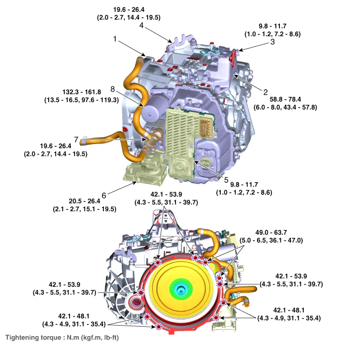
1. Dual clutch transmission
2. Transmission mounting bracket
3. Position switch
4. Shift cable bracket
5. Dual clutch transmission control module (TCM)
6. High Flow Electric Oil Pump (HF EOP)
7. Oil cooler module
8. Accumulator

• Be careful not to damage the parts located under the vehicle (floor under cover, fuel filter, fuel tank and canister) when raising the vehicle using the lift.(Refer to General Information - "Lift and Support Points")
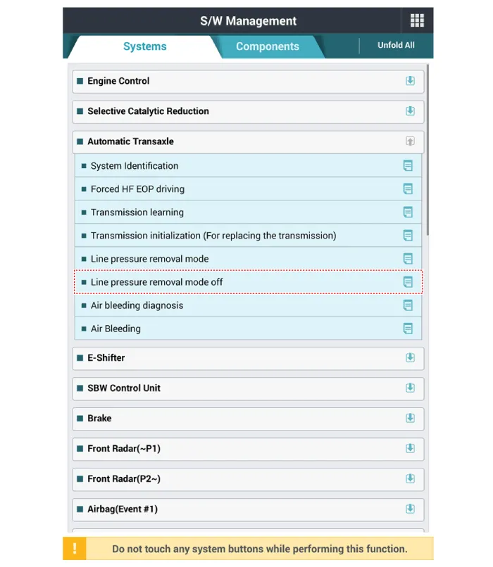
1.Perform the line pressure removal mode off procedure by using the diagnostic tool.
2.Remove the air cleaner assembly and air duct.(Refer to Engine Mechanical System - "Air cleaner")
3.Remove the ECM.(Refer to Engine Control / Fuel System - "Engine Control Module (ECM)")
4.Remove the battery and battery tray.(Refer to Engine Electrical System - "Battery")
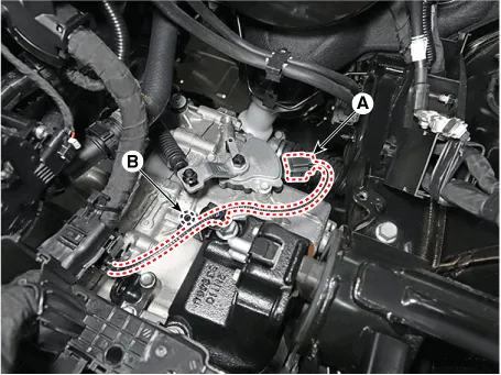
5.Disconnect the position switch connector (A) and then loosening the mounting bolt (B).
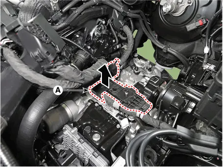
6.Disconnect the wiring bracket (A).
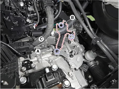
7.Remove the shift cable (C) after loosening the nut (A) and bolts (B).
Tightening torque : (A) : 9.8 - 13.7 N.m (1.0 - 1.4 kgf.m, 7.2 - 10.1 lb-ft)(B) : 19.6 - 26.5 N.m (2.0 - 2.7 kgf.m, 14.5 - 19.5 lb-ft)
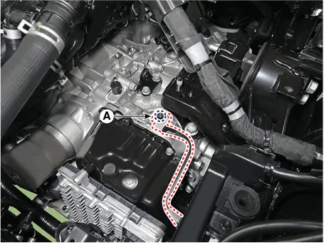
8.Loosen the bolts and then remove the ground line (A).
9.Loosen the transaxle upper mounting bolts (A) and the starter mounting bolts (B).
Tightening torque :(A) 42.2 - 54.0 N.m (4.3 - 5.5 kgf.m, 31.1 - 39.8 lb-ft) (B) 49.0 - 63.7 N.m (5.0 - 6.5 kgf.m, 36.2 - 47.0 lb-ft)
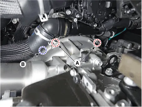
10.Disconnect the intercooler inlet hose (A).
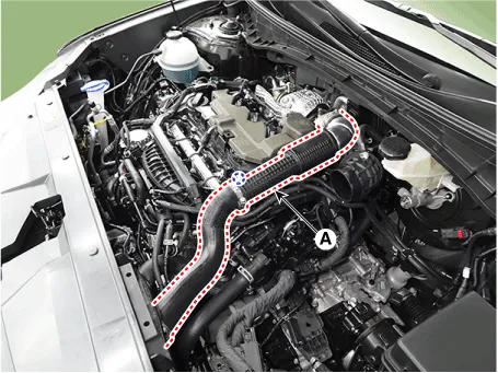

• When separate the intercooler inlet pipe, pull out the quick connector clamp (A).
• When working with quick connector type intercooler hoses and pipes, be careful not to touch or detach the rubber seal (B) inside.
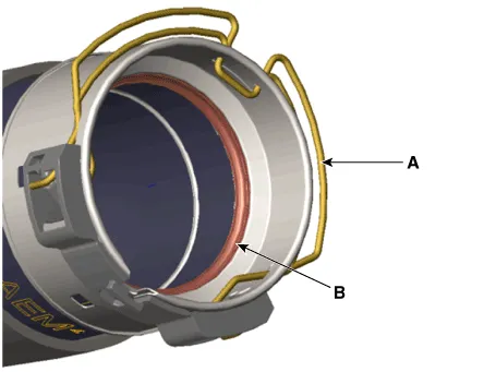
• When installing, Align the marks of the intercooler pipes/hoses and assembling parts.
• When mounting, Install it by pushing it all the way until the nipple clicks.
11.Disconnect the oil cooler hose (A).

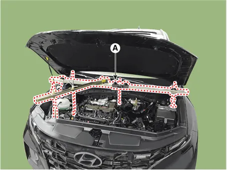
12.Assemble the engine support fixture use a (Beam SST No.: 09200 - 3N000, Adapter SST No.: 09200-2W000, Engine support fixture (supporter) SST No.: 09200-2S200, Engine support fixture (front) SST No.: 09200-L1200.
13.Using the engine support fixture (A), hold the engine and transaxle assembly safely.
14.Remove the front wheel guard.(Refer to Body (Interior and Exterior) - "Front Wheel Guard")
15.Loosen the transmission bracket support mounting bolts (A).
Tightening torque :107.9 - 127.5 N.m (11.0 - 13.0 kgf.m, 79.6 - 94.0 lb-ft)
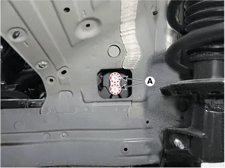
16.Loosen the transaxle support bracket mounting bolts and then removing the transaxle support bracket (A).
Tightening torque :58.9 - 78.5 N.m (6.0 - 8.0 kgf·m, 43.4 - 57.9 lb-ft)
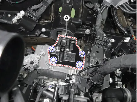
17.Remove the engine room under cover.(Refer to Engine Mechanical System - "Engine Room Under Cover")
18.Remove the sub frame.(Refer to Suspention System - "Front Sub Frame")
19.Remove the driveshaft assembly. (Refer to Driveshaft and Axle - "Front Driveshaft")
20.In case of 4WD vehicle, remove the transfer assembly.(Refer to 4 Wheel Drive (4WD) System - "Front Wheel Transfer Assembly")
21.Drain the coolant by loosening the drain plug.(Refer to Engine Mechanical System - "Coolant")
22.Disconnect the oil cooler hose (A).
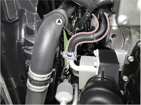
23.Disconnect the TCM connector (A).
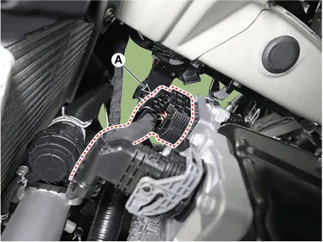
24.Disconnect the high pressure electric oil pump (HP EOP) connector (A).
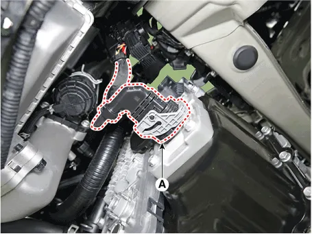
25.Loosen the wiring bracket mounting bolts (A).
Tightening torque :9.8 - 11.7 N·m (1.0 - 1.2 kgf·m, 7.2 - 8.6 lb-ft)
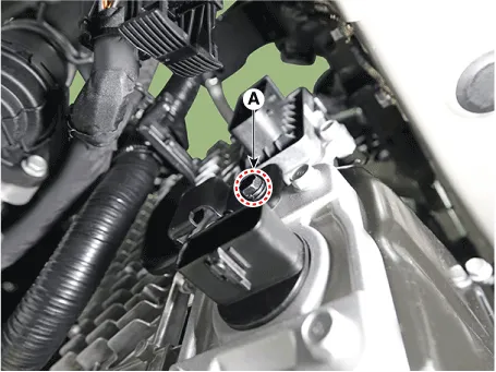
26.Disconnect the high flow electric oil pump (HF EOP) connector (A).

• If cooling gets into the HF EOP connector, corrosion may occur inside the connector, thus causing an open/short circuit. In this case, trouble codes and shift failure may also occur.
• After disconnecting the connector, wrap the HF EOP male connector and female connector with clean plastic to prevent coolant form flowing the connector.
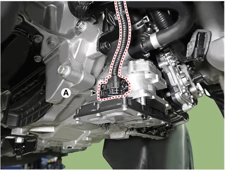
27.Loosen the wiring bracket mounting bolts (A).
Tightening torque :9.8 - 11.7 N·m (1.0 - 1.2 kgf·m, 7.2 - 8.6 lb-ft)

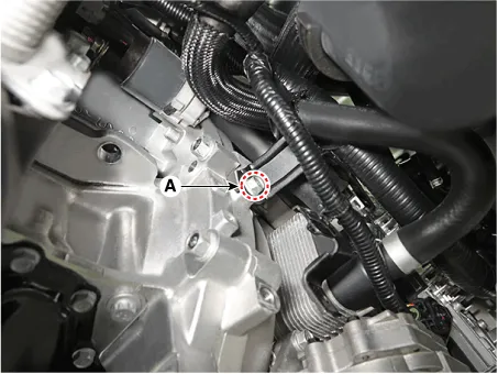
28.Loosen the starter mounting bolts (A).
Tightening torque :49.0 - 63.7 N.m (5.0 - 6.5 kgf.m, 36.2 - 47.0 lb-ft)
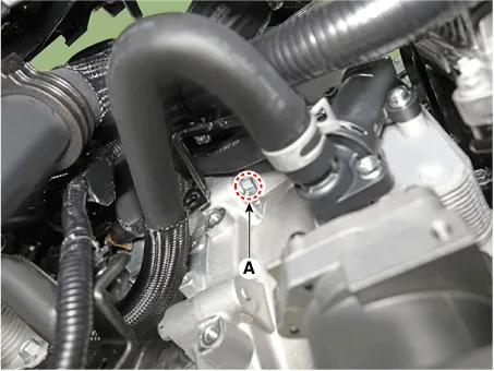
29.Loosen the bolts and then removing the roll rod support bracket (A).
Tightening torque :49.0 - 68.6 N.m (5.0 - 7.0 kgf.m, 36.2 - 50.6 lb-ft)

30.Loosen the bolt and then removing the dust cover (A) and then support the transmission with a jack
Tightening torque :42.2 - 48.1 N.m (4.3 - 4.9 kgf.m, 31.1 - 35.4 lb-ft)
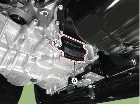

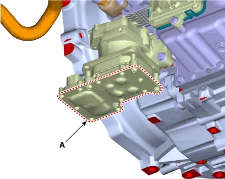
• Make sure that the bottom of HF EOP inverter (A) does not touch the jack.
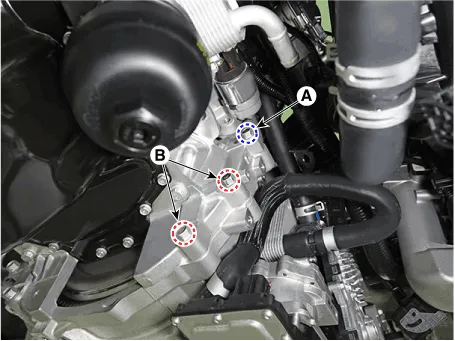
31.Loosen the transmission lower mounting bolts (A, B).
Tightening torque :(A) 42.1 - 53.9 N·m (4.3 - 5.5 kgf·m, 31.1 - 39.7 lb-ft) (B) 42.2 - 48.1 N.m (4.3 - 4.9 kgf.m, 31.1 - 35.4 lb-ft)
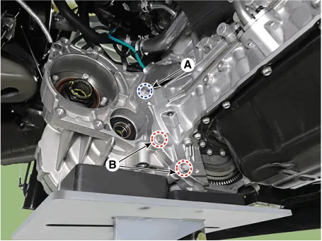
32.After separating the transmission from the engine, remove the transmission by lowering the jack slowly.

• Make sure that the HF EOP inverter does not touch the floor.
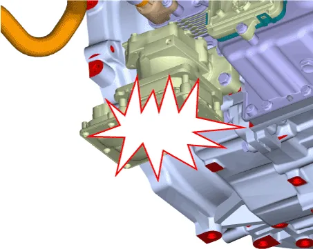
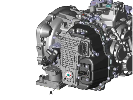
33.Remove the TCM assembly, when reusing the TCM.
(1)Remove the TCM connector bolt (A).
Tightening torque :7.8 - 9.8 N.m (0.8 - 1.0 kgf.m, 5.8 - 7.2 lb-ft)
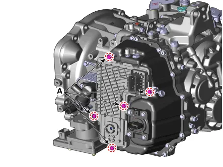
(2)Remove the TCM bolts (A).
Tightening torque :9.8 - 11.7 N.m (1.0 - 1.2 kgf.m, 7.2 - 8.6 lb-ft)
(3)Remove the TCM assembly (A).
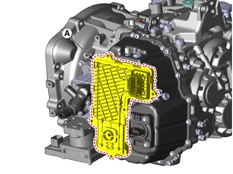

• Be careful not to damage the TCM pin part (A) when removing the TCM assembly.
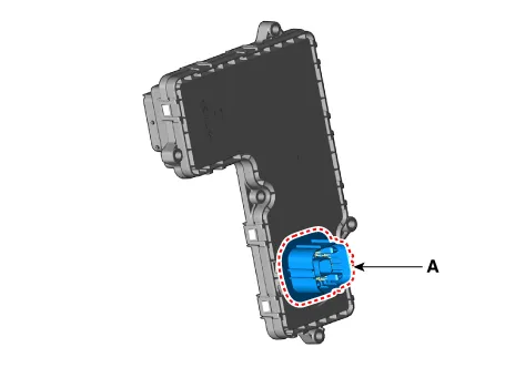
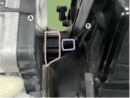
• Make sure the TCM pin part (A), and E-module part (B) fit when installing.
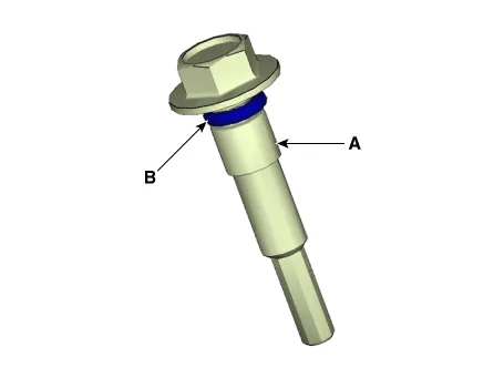
• When reinstalling the TCM, must be replaced the TCM connector moungting bolt (A) with new one and apply the oil to the O-ring (B) before tightening it.
1.To install, reverse the removal procedure.

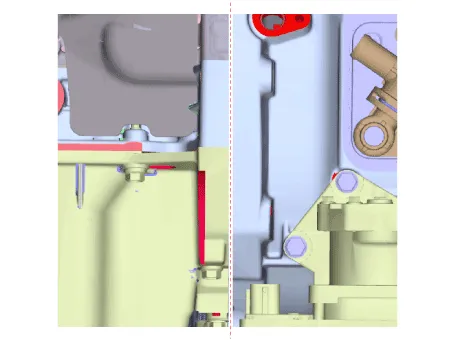
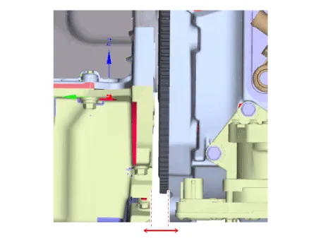
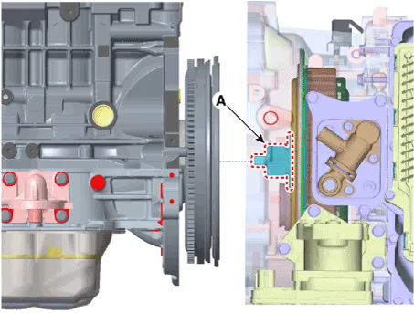
• Matters that require attention when installing the dual clutch transmission (DCT) to engine(1) Apply grease CASMOLY L9508 0.2 to 0.3g in a circular direction upto 10 mm point from the end of the input shaft spline.(2) Check the pilot bearing on the side of engine for any dents, damages and deformations before installing the DCT.(3) Install the transmission to the engine after aligning the input shaft (A) and engine pilot bearing.
| Correct | Incorrect |
|
|
• Perform the procedure below after installing the transmission. (1) The new DCT is already filled with the specified amount of oil. For this reason, it is not necessary to refill and check the oil. (2) If the differential oil seal is damaged and oil is leaking, replace the oil seal with a new one by using the special service tools.
| Item | SST | |
| Installer | Handle | |
| Case side differential oil seal | 09453-3L240 | 09231-H1100 |
| Clutch housing side differential oil seal (2WD) | 0K431-P2100 | 09231-H1100 |
| Clutch housing side differential oil seal (4WD) | 09430-2C800 | 09231-H1100 |
| Transfer driven gear oil seal (4WD) | 09473-D3500 | 09231-H1100 |
(3) If occured oil leakage, check the oil level after refilling the DCT with oil.(Cooling System - "Dual Clutch Transmission Lubricant / Cooling Oil")(Hydraulic System - "Dual Clutch Transmission Control Fluid")

• There is no need to check the oil level as the new dual clutch transmission assembly is completely filled with oil.
• If a remanufactured DCT transmission is installed, check the gear oil level after filling the 2.5 ℓ (0.66 U.S gal., 2.64 U.S.qt., 2.20 Imp.qt.).
• If the control oil level is low, replace the transmission body.
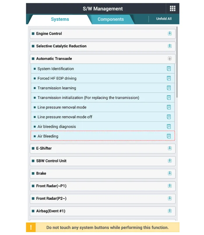
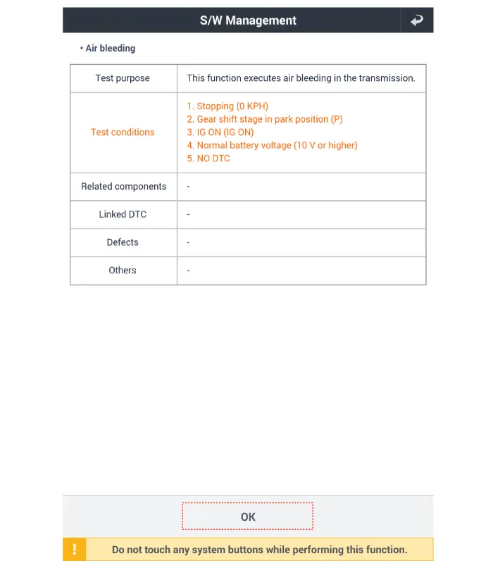
(4) Clear the diagnostic trouble codes (DTC) using the diagnostic tool. Even though disconnecting the battery negative Pin, the DTCs will not be cleared. So, be sure to clear the DTCs using the diagnostic tool.2.Perform the air bleeding procedure by using the diagnostic tool.
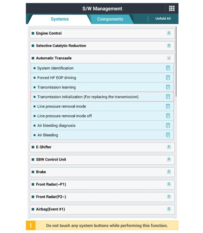
3.Perform the factory mode exit procedure by using the diagnostic tool if replaced transmission with a new one.
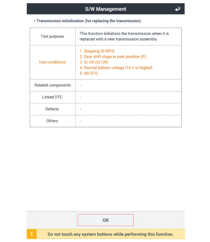
4.Perform the DCT learning procedure by using the diagnostic tool if reused the TCM. (If replaced the transmission only)Perform the work procedures for DCT learning procedure by referring to the table below.
| Item | Remanufactured DCT | NEW DCT |
| DCT (With TCU) | Performed | Not performed |
| DCT (Without TCU) | Performed | Performed |
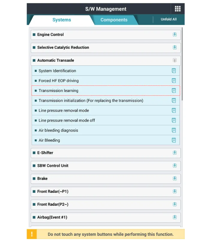
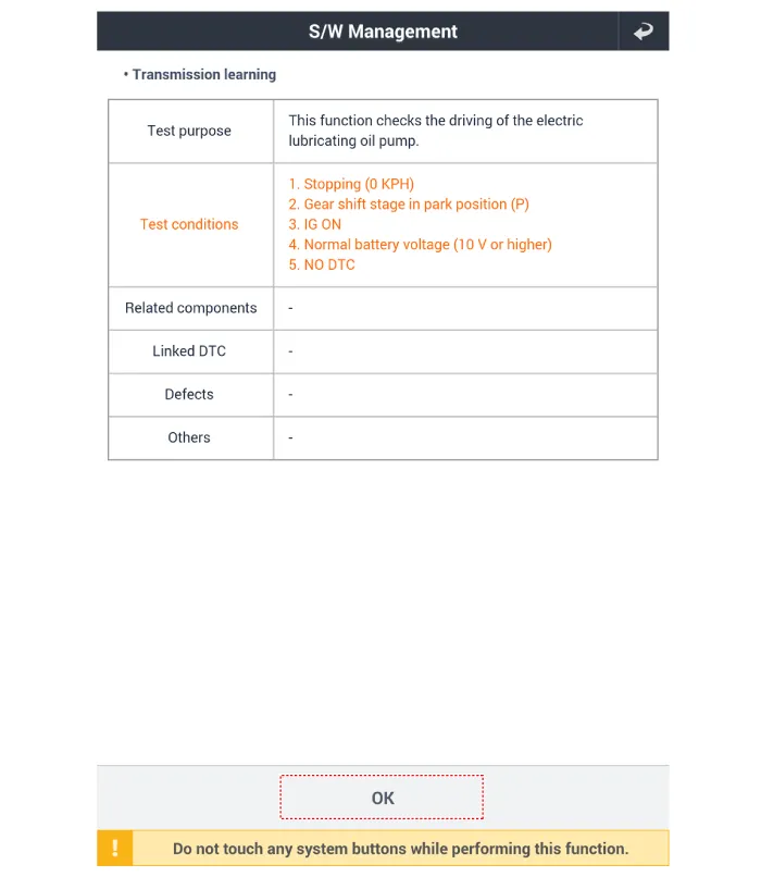
5.Perform the touchpoint curve learning procedures.
• Perform to learn a touchpoint curve.
(1)Drive the accelerator pedal at a low angle after starting from a stop condition P → D, P → R (Drive while accelerating pedal from 10% to 30% and gradually increasing)
(2)Drive the accelerator pedal at a middle angle after starting from a stop condition P → D, P → R (Drive while accelerating pedal from 30% to 50% and gradually increasing)

• An accelerator pedal angle doesn't need to be driven exact but needs to drive while gradually increasing the angle to ensure a good learning procedure.
(3)Repeat the above procedure. (Test time 2 min)
6. Re-perform the touchpoint curve learning procedures after DCT learning procedure, when there is delayed acceleration or shift shock occurs. (Maximum 5 time)
 Hydraulic System
...
Other information:
Hyundai Santa Cruz (NX4A OB) 2021-2025 Service Manual: Oil Pressure & Oil Temperature Sensor (OPTS)
- Description
It generates the oil pressure and temperature information (output
voltage) to control the pump operation proportional control valve in
variable oil pump system.It measures the oil pressure and temperature
discharged from the oil pump and transmits the pressure information to
...
Hyundai Santa Cruz (NX4A OB) 2021-2025 Service Manual: Specifications
- Specifications
ItemSpecification
TypeElectric Power Steering System
Steering gearTypeRack & Pinion
Rack stroke152 ± 1 mm (5.98 ± 0.04 in)
Steering angle (Max.)Inner36.9˚ (+0.5˚/-1.5˚)
Outer32.1°
- Tightening torque
ItemTightening torque (kgf.m)
N.mkgf.mlb-ft
Tire wheel H ...

