Hyundai Santa Cruz: Audio/AVNT System / Display Audio Unit
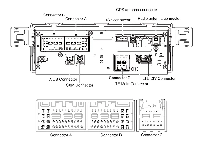
| No | Connector A (Internal Amplifier) | Connector A (External Amplifier) | Connector B | Connector C |
| 1 | Rear door speaker LH (+) | - | - | - |
| 2 | Rear door speaker LH (-) | - | Mic1 (+) | I -CAN (High) |
| 3 | - | Navigation voice (+) | - | - |
| 4 | - | External amplifier SPDIF (+) | - | - |
| 5 | Reset | Reset | - | - |
| 6 | Camera power (OPT) | Camera power (OPT) | Illumination (+) | - |
| 7 | Camera video (OPT) | Camera video (OPT) | M-CAN (High) | - |
| 8 | - | - | - | - |
| 9 | - | - | - | I -CAN (Low) |
| 10 | - | - | Battery (+) | - |
| 11 | USB DETECT | USB DETECT | Battery (+) | - |
| 12 | Steering wheel remote | Steering wheel remote | Ground | - |
| 13 | Front door speaker LH (+) | - | Ground | - |
| 14 | Front door speaker LH (-) | - | - | - |
| 15 | Front door speaker RH (-) | - | Mic1 (-) | - |
| 16 | Front door speaker RH (+) | - | Camera equipment detect 2 | MTS |
| 17 | - | Navigation voice (-) | - | - |
| 18 | - | External amplifier SPDIF (Low) | - | - |
| 19 | - | External amplifier SPDIF (Ground) | Illumination (-) | - |
| 20 | Camera power ground (OPT) | Camera power ground (OPT) | M-CAN (Low) | - |
| 21 | Camera video ground (OPT) | Camera video ground (OPT) | - | - |
| 22 | - | - | ACC | |
| 23 | - | - | Keyboard power | |
| 24 | - | - | Front monitor power | |
| 25 | - | - | - | |
| 26 | Steering wheel remote ground | Steering wheel remote ground | - | |
| 27 | Rear door speaker RH (-) | - | - | |
| 28 | Rear door speaker RH (+) | - | - | |
| 29 | - | - | - | |
| 30 | - | - | - | |
| 31 | - | - | - | |
| 32 | Camera equipment detect 1 | Camera equipment detect 1 | - | |
| 33 | - | - | IGN 1 | |
| 34 | - | - | Keyboard ground | |
| 35 | - | - | Front monitor ground | |
| 36 | - | - | ||
| 37 | - | - | ||
| 38 | Vehicle speed | Vehicle speed |
1.Disconnect the negative (-) battery terminal.
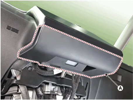
2.Remove the front monitor lower cover (A).
3.Remove the front monitor lower cover after disconnecting the mood lamp connector (A).
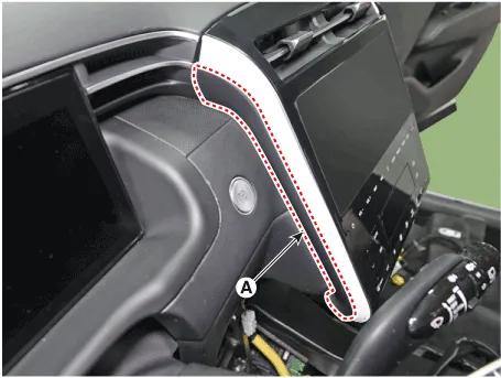
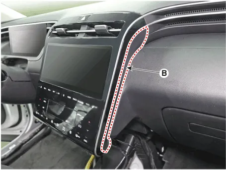
4.Remove front monitor side cover (A) and (B).
5.Remove the front monitor assembly (A).
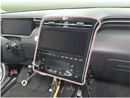
6.Remove the front monitor assembly (A) after disconnecting monitor connectors.
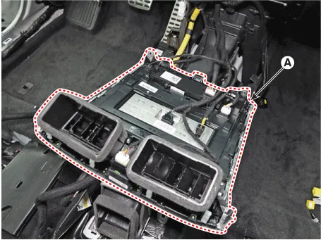
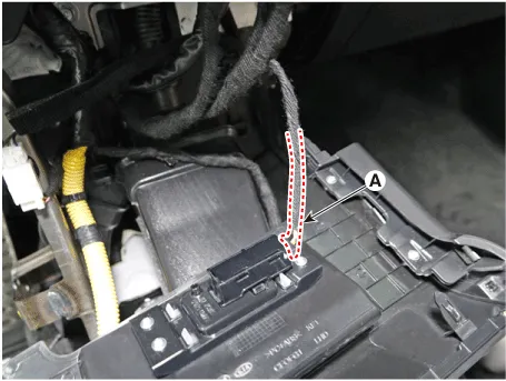
7.Remove the audio unit (A) after loosening mounting screws.
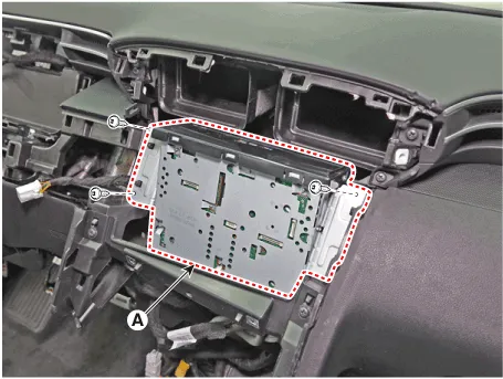
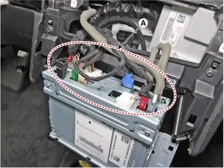
8.Remove the audio unit after disconnect audio connectors (A).

• Because the repair procedure is the same as the AVN head unit, we used the AVN head unit repair procedure image.
1.Install audio connectors and antenna connectors.
2.Install the audio unit.
3.Install the front monitor assembly.
4.Install the front monitor side cover.
5.Install the front monitor lower cover.
6.Connect the negative (-) battery terminal.

• Make sure the connector are connected in properly.
• Check the audio system for normal operation.
 AVN Head Unit
- Components
NoConnector A (ExternalAmplifier)Connector A (Internal Amplifier)Connector BConnector C
1- Rear door speaker LH (+)Mic2 (+) -
2- Rear door speaker LH (-)Mic1 (+) I -CAN (High)
...
 External Amplifier
- Components
Connector Pin Information
NoConnector AConnector B
1Battery (+)Front right door tweeter speaker (+)
2Battery (+)Front left door tweeter speaker (+)
3Battery (+)Sub woofer speake ...
Other information:
Hyundai Santa Cruz (NX4A OB) 2021-2025 Service Manual: Joint Assembly (Transaxle side)
- Removal
• Drive shaft joints require special grease, so do not add any other type of grease.
• When replacing the boot band, it must be a new one.
1.Remove the front drive shaft.(Refer to Driveshaft Assembly - "Front Driveshaft")
2.Remove the transaxle side large ...
Hyundai Santa Cruz (NX4A OB) 2021-2025 Service Manual: Specifications
- Specifications
ItemSpecification
TypeElectric Power Steering System
Steering gearTypeRack & Pinion
Rack stroke152 ± 1 mm (5.98 ± 0.04 in)
Steering angle (Max.)Inner36.9˚ (+0.5˚/-1.5˚)
Outer32.1°
- Tightening torque
ItemTightening torque (kgf.m)
N.mkgf.mlb-ft
Tire wheel H ...
